This last week I have been focussing on creating a fully functioning prototype. This would involve having a system which I could plug when and, without my interference, it would be able to perform the full motions of the leg movement. Unfortunately I have not yet got up to that point, however, I have got up to the point of printing a small chassis just for a single leg. All the wiring and proper securing of parts was done, so I now have two servo motors, one with a leg, and one with a pulley. While these worked independently, I needed to test if they would work together. I cut some of the actual belt, and put the clamp on as to create a closed loop. This would allow me to put both parts of the pulley inside and apply tension when the system is active. When this happened, I was able to see that the system worked to an extent. While the leg was doing what I had wanted it to do, it wasn’t extremely reliable. There were to main reasons for this; one being the lack of strength that the leg had on its motor. This was fixed by hot-gluing the leg to the plastic which was screwed into the bearing, although initially into a broken motor. The second problem was due to friction. This is no fault of my design, but more my execution of it. When i created holes for an axel to go through, I did it through each part separately, and on different days. With very poor measurements, this meant that the holes did not line up exactly. While this didn’t stop the legs from spinning entirely, it meant I had to apply a lot more tension then I had intended. Luckily, this is a problem that can easily be fixed in the next stage when I print it again.
Other than this, I have been designing a chassis for the single leg to be attached to. This design took some time and lots of measuring. But I eventually came to a final design that I need to convert into a Fusion STL from a drawing on paper.
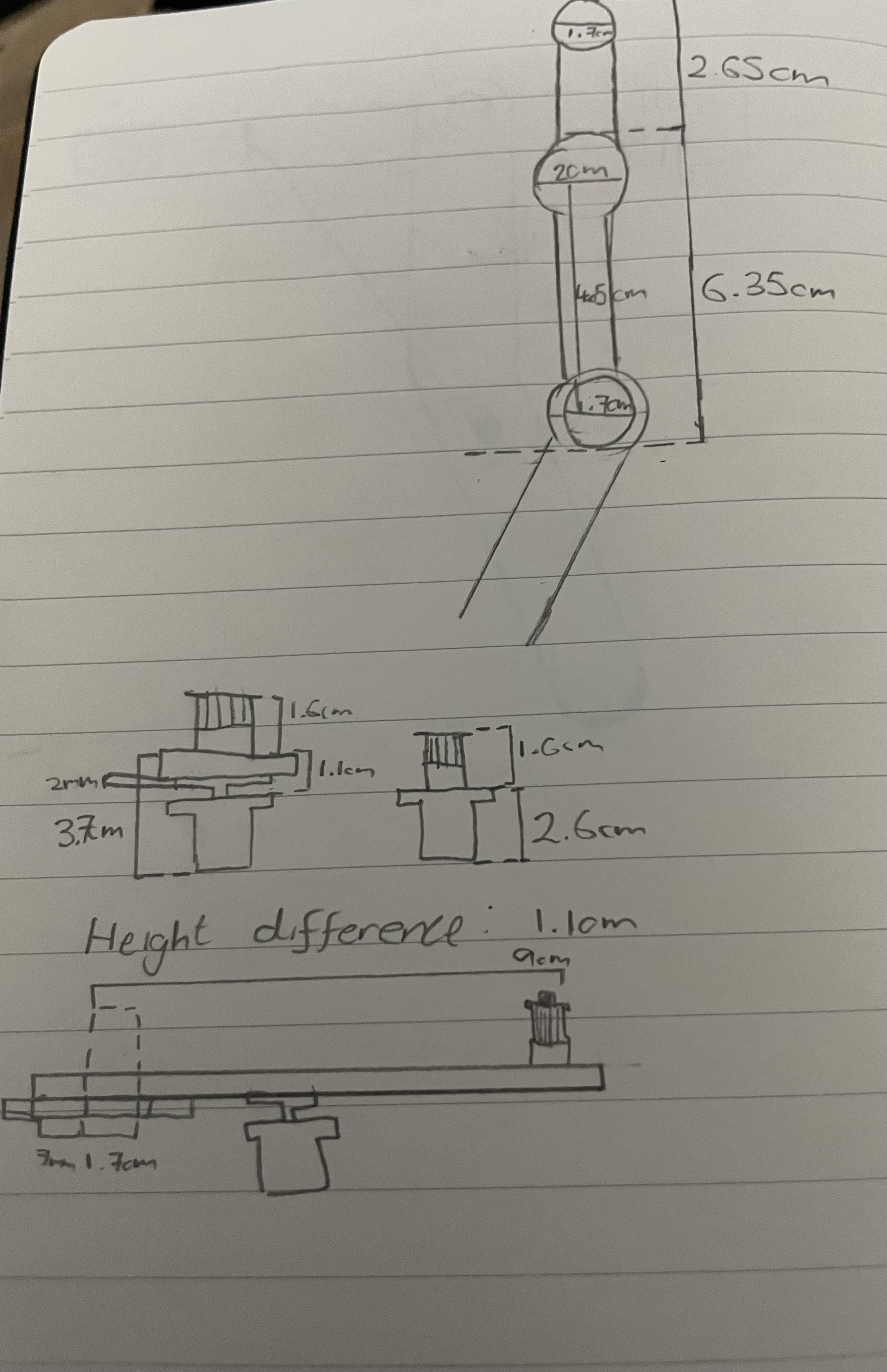
This design arose from the problem that there needed to be enough tension on the pulley to prevent slack in the belt. While considering this, however, I realised that the simple design of have two servo mounts on a static plate would not be sufficient for my leg design. This is because the upper pulley servo needs to be attached above the leg, as it doesn’t have room to be placed over the turning point. But this causes the problem of an inconsistency when looking at centre to centre distances of the two pulleys. As the leg rotates, the distance between them changes, thus creating a varied requirement of belt length dependent on the angle of the leg. My new design seen above finds a solution in connecting the servo to a mount that moves relative to the rest of the leg.
I do feel that I am slightly behind where I would like to be with this project, as I was planning on having the chassis printed by the end of this week, which hasn’t happened. However, I anticipate that this project will get a lot faster after this is designed the first time, as I need to test one, then merely replicate it three more times once it works. I do need to be cautious of the fact that I will need time to apply all the legs to the final version of the robot, but I feel that I will have enough time for that if I am able to get the chassis done early in the coming week.