Overview
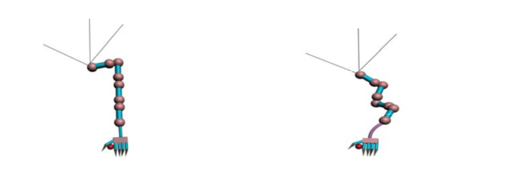
In this first week of Year 12 Robotics, I was given an overview of the semester and all the tasks within it. With three assessable items, being this blog, a midterm test, and a major project presentation, I will spend most of my time this term working on the latter. I have chosen to continue with my project from last year; a quadrupedal robot named Winston. In Winston’s second rendition, I improved the design of his legs to involve two joints, and I attempted to replicate real muscle movement. I was very happy with how that turned out, and eager to continue to improve Winston. This semester, I am planning on making some inverse kinematics software. This algorithm should allow reliable movement for Winston across various types of terrain, by assuming an endpoint, working out the movements required to get there, then adjusting at every stage.
Work I have completed
Even though it is the beginning of the year, I have already completed a decent amount of work. I got a start reading through a couple reports and journals which I will probably end up using for the final project. There were two reports that I read through and found helpful. I initially started looking for other people who have used IK in other projects, and I came across a report by Wei Song, which discussed two methods of IK, one being trigonometric, and one being cyclic. The Cyclic Coordinate Descent method proved to be better for my purpose, as the main difference is how it updates very frequently and gradually improves how each joint is relative to its target.
I then wanted to see how I would apply the CCD mathematically, which lead me to a report by Ankan Saha. I read the early pages of this report about 6 times before deciding to ignore the maths because it looked hard. I did learn more about the basic parts of CCD through this, however.
At this point I decided to start working on a rough simulation for IK. My goal for this simulation was to have a moveable target which was solved and displayed visually, and then to attempt to apply this to real servo motors. To do this I decided to use Pygame, as it would be easy to visualise, and it has the ability to easily do vector math which would make this problem a lot simpler. The function which solved the IK is very simple. It attempts to make the final vector as close to the target as it can, and then moves the next one to do the same. It will then reposition the first, second, and move onto the third. This repeats until it reaches the target. With only needing two vectors, however, this is very simple to do.
 1.  def solve_ik(i, endpoint, target):
 2.     '''Function to calculation IK'''
 3.     if i < len(points) - 2:
 4.         endpoint = solve_ik(i+1, endpoint, target)
 5.     current_point = points[i]
 6.
 7.     angle = (endpoint-current_point).angle_to(target-current_point)
 8.     angles[i] += min(max(-3, angle), 3)
 9.     angles[i] = min(max(180-max_angle, (angles[i]+180)%360), 180+max_angle)-180
10.
11.     return current_point + (endpoint-current_point).rotate(angle)
 1.  while 1:
 2.     for event in pygame.event.get():
 3.         if event.type == pygame.QUIT: sys.exit()
 4.
 5.     solve_ik(0, points[-1], target)
 6.     angle = 0
 7.     for i in range(1, len(points)):
 8.         angle += angles[i-1]
 9.         points[i] = points[i-1] + rel_points[i-1].rotate(angle)
10.         calcAngle(angle)
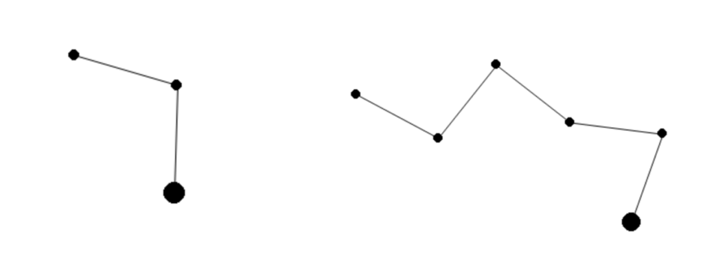
When visualised, the vector was successfully able to find the target, which followed the mouse and updated in real-time.
The next step is to apply this to real motors, which will occur next week, however, I have worked on an Arduino which took incoming data from the python program, using the serial library, and knew which servo to move and what angle to move it to.
1. if(Serial.available() > 0) {    // see if there's incoming serial data
3.     for(int i=0; i<2; i++) {
4.       incomingByte[i] = Serial.read(); // read the oldest byte in serial buffer
Although I have written the code, I have been unable to test it in turning motors.
Overcoming Challenges
Converting this into real movement shouldn’t be overly difficult, after all, the angle of each joint is recorded and added to a list. There were two major problems to solve in this, however. The first is that the speed at which this updates may be too high for servo motors to cope with. This shouldn’t be too hard, as I can either change the frame-rate and limit data in, or only send signals through once a final destination has been calculated. The second is due to there being multiple angles, both under the same variable, it is difficult to know which motor should be assigned which variable. This was solved by adding a simple function named assign_angle() which, as each angle is calculated, checks a counter by doing i%2 and checks if i is even or odd. Ifi is odd, then the angle must be on the first joint, otherwise it is on the second. Implementing the real movement now should be easy. And, after adding these changes and running into other errors with the Serial library, it was relatively straightforward.
Reflection
This was a very good first step for me. Although the simulation was very rough, and still needs a lot of work, having this in the first week allows me to do a lot more in the coming weeks, and has given me a better understanding of what I am undertaking earlier on, which will hopefully help me manage my time better. I also did this simulation completely independently. This shouldn’t be unexpected but being in the first week back at school and going straight into vector math and trig, with the help of online articles, I was able to complete and fix the problems as they came. Next, I will likely attempt to adapt this existing program to be able to calculate for two legs simultaneously, as when that is solved it should be simple to add all four.