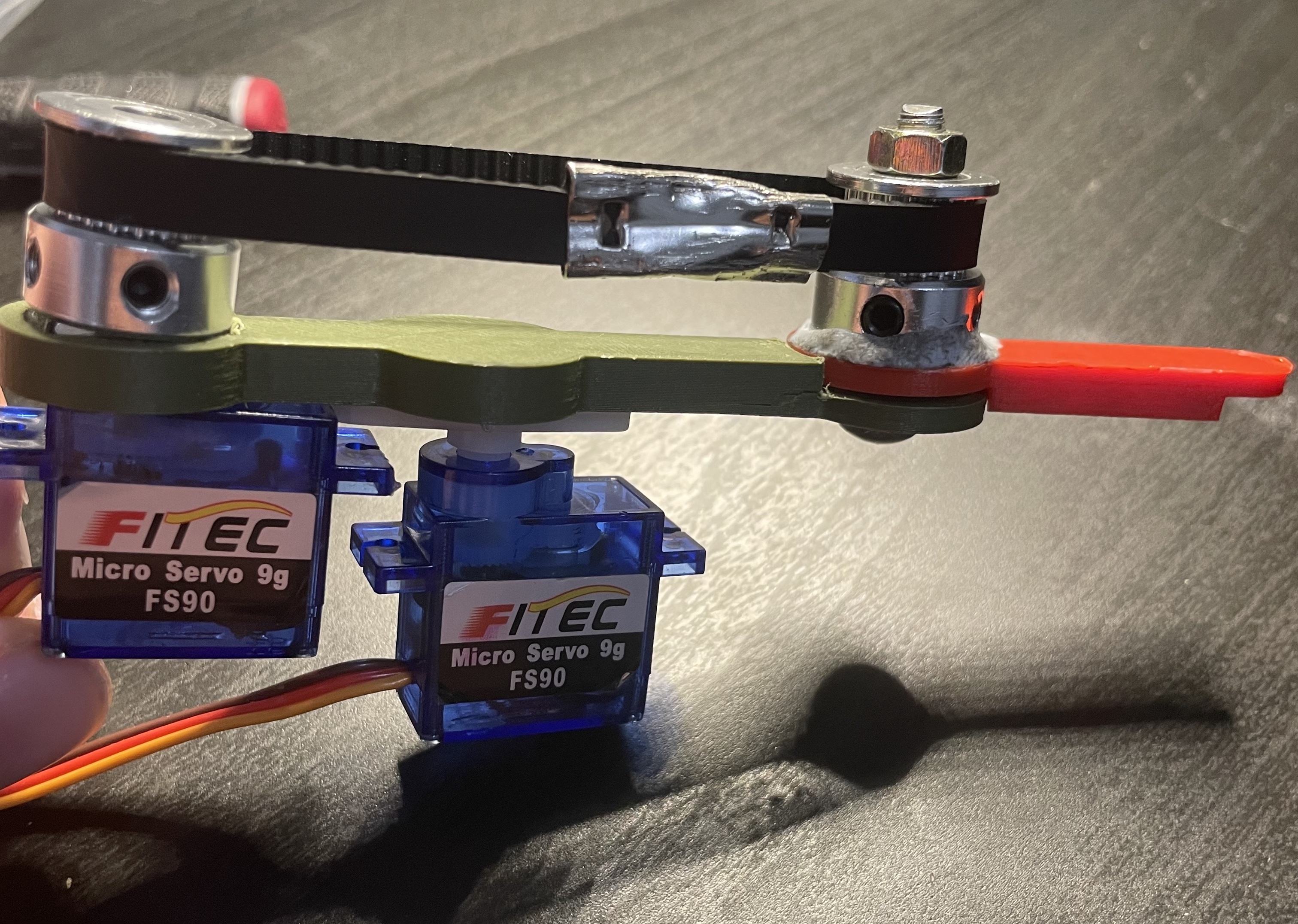
This week I have been focussed on producing a final version for my quadruped leg design. At first, I was running far behind schedule, and I was getting worried that I wouldn’t be able to complete this task in time. At one point, when I needed to 3D print a new design for the leg, I was unable to go one day, tried the next day only to find out I needed to try again the day after because I used ‘Ninjaflex’ instead of PLA. The issue there is that Ninjaflex is rubbery, and so it holds no shape when tension is applied pulling it inwards. I did manage to get a PLA print the third day, however this was very behind where I wanted it to be as I was planning on having this done Sunday – 3 days prior. After I got the print, I assembled it with the servo motors and second part of the leg. I had already tested to find that the servo motors were capable of moving the belt I planned on using, and so I just needed to put it together with the rest of the leg. I needed to recut the belt since the length in testing was different to the length used in the final design, but that didn’t take too long, and was just finicky. Once the entire leg was constructed, there was one more physical issue that arose – the tension of the belt pulled the lower leg into the upper one, causing more friction than was accounted for in the design. This caused large issues when considering the lower leg axel hole wasn’t exactly centred, and so there was already more friction than desired. Because of this, the leg failed to turn. I decided to sit there for a while and file down the bearing, in hopes to create more space thus reducing friction. This took a while, but did end up working. I got the lower leg to be able to spin with relative ease with the motor. There are still some parts which aren’t smooth enough to turn nicely, however, it works for the distance it is required to turn. Another issue that arose was the method of connected one of the pulleys to the servo. The diameter of the screw used for the motor happened to be the exact same as the inner diameter of the pulley, meaning if it where forced in there, it was able to stay. It was pushed too far in though, and not enough of the screw was exposed to connect to the motor securely. I managed to get this out and redo it and it now works well. After all this was done, I realised that the leg itself didn’t fit within the requirements of the task, as it had no analog to digital signals. I fixed this by adding a potentiometer and modifying the code to make the position of the leg relative to the position of the potentiometer. This was an easy fix and was done well within half an hour.
Upon the conclusion of the circuitry, the physical element of the task seemed complete, and I just needed to write the report. The report was surprisingly fun to write, and allowed me to collate all the physics and designing that went into this project. I have completed all parts of this robot up to the standard of which is submittable, however I was advised to add a model chassis to the leg to give clear insight into how this would be applied to the robot itself.